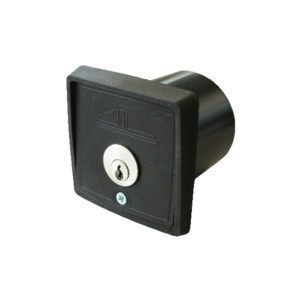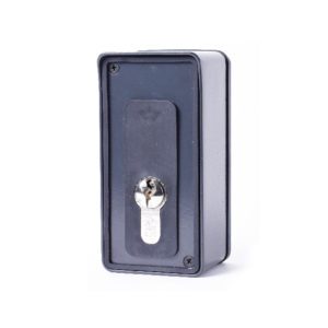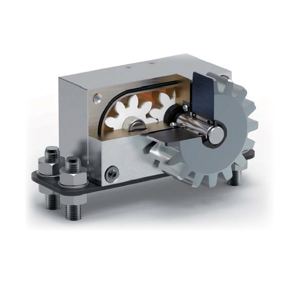
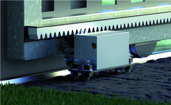
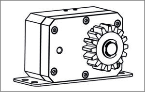
The CONTROLGIR line is indispensable for standardization in the presence of sliding gates on a slope ( it is necessary for there to be a rack). In case of unlocking of the automation gear motor, the internal hydraulic circuit (adjustable) has the function of “parachute,” that is, to regulate the downward speed throughout the gate’s travel. The operating speed should be adjusted just above that of the gearmotor so that it does not interfere with the automation.
CONTROLGIR-7
Braking system for sloping sliding gates – maximum slope 3,2° (7 Mn)
TECHNICAL DATA
M (required resistant moment): 7 Nm
Rack pitch: M4
Gate weight: 400 Kg (3920 N)
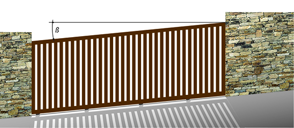
Slope: 3,2° MAX
Formula:
M [Nm] = P x sinß x 0,032
P = gate weight in Newtons (9.8N=1Kg)
sinß = sine of the tilt angle (ß= tilt in degrees)
P = 9.8 x 400kg = 3920 Newton
M = 3920 Newton x sin 3.2 x 0.032 = 7 Nm
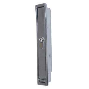
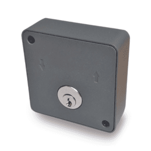
CONTROLGIR-30
Braking system for sloping sliding gateCsO – mNaTxRimOuLmG IsRlo-p3e0 1 (33,90°N (3m0 )Nm)
TECHNICAL DATA
M (required resistant moment): 30 Nm
Rack pitch: M4
Gate weight: 400 Kg (3920 N)
Slope: 13,9° MAX
Formula:
M [Nm] = P x sinß x 0,032
P = gate weight in Newtons (9.8N=1Kg)
sinß = sine of the tilt angle (ß= tilt in degrees)
P = 9.8 x 400kg = 3920 Newton
M = 3920 Newton x sin 13.9 x 0.032 = 30 Nm
Data Sheet
Controlgir-7 Instructions manual
Controlgir-30 Instructions manual
REQUEST INFORMATION